How to Choose a Directional Antenna in 2026?
Choosing a Directional Antenna in 2026 starts with a clear question: what signal must it receive or transmit, and from where? A model designed for a fixed point-to-point link may not suit a moving receiver or a crowded urban site. Match the antenna’s frequency range to the equipment and signal you actually use. Then consider gain, beamwidth, polarization, connector type, and mounting options. Small details matter.
Higher gain can help reach a distant signal, but it usually narrows the beam. That means careful alignment becomes more important. Check the manufacturer’s radiation pattern, not just the headline gain figure. A rooftop installation, for example, may face wind, nearby buildings, and a long cable run. Each can affect the result. No universal winner.
Reliable selection also means checking the whole system. Confirm that the antenna, cable, connectors, and radio are compatible, and account for cable loss where relevant. Compare published specifications from established manufacturers, while treating performance claims cautiously when test conditions are unclear. Local rules and safe installation practices may also apply, so verify requirements for your location and equipment. A datasheet cannot predict every site. Even a careful comparison can miss an obstruction or an alignment problem; measuring signal quality after installation is a useful reality check. This guide explains the trade-offs, practical questions, and common selection mistakes to consider before choosing a directional antenna in 2026.
Define Your Coverage Needs and Operating Requirements
Before choosing a directional antenna, define the area that must receive a usable signal. Sketch the site, mark the transmitter, and note obstacles such as metal walls, tree lines, and nearby buildings. Specify the required range, frequency band, bandwidth, and whether coverage must reach one fixed point or several locations. A narrow beam can improve signal in one direction, but may leave nearby work areas poorly served. Small detail, big impact.
The Ericsson Mobility Report, June 2024, estimated that global mobile network data traffic grew 25% between the first quarters of 2023 and 2024. That growth does not determine your antenna, but it reinforces the need to plan for actual capacity and operating conditions—not distance alone. Record the expected number of connected devices, peak usage times, and available mounting position. Then check the radio link budget, including cable loss, connector loss, antenna gain, and receiver sensitivity. A long cable can quietly erase useful gain.
Test at the intended mounting height and in the direction of the target area whenever possible. Compare readings at several points, including indoor edges and outdoor dead zones. I have seen map-based estimates look convincing, then fail behind a single concrete wall. Recheck after seasonal foliage changes if trees lie in the signal path. Note the uncertainty. Your coverage target may need adjustment once real measurements expose gaps.
Match the Antenna to the Frequency Band and Signal Type
A directional antenna should match the signal’s frequency band before you compare gain figures. Check the equipment’s specifications, not just its product label. A model designed for 2.4 GHz may perform poorly at 5 GHz, even if its shape looks suitable. The antenna’s stated range should cover the frequencies you actually use, with enough bandwidth for the full channel.
Signal type matters, too. Wi-Fi, cellular, and point-to-point radio links may use different bands, polarization, and channel widths. The antenna does not decode a signal, but its design must support the signal’s frequency and polarization. A mismatch can weaken reception. Check whether the system uses horizontal, vertical, or dual polarization, then align the antenna accordingly. Small alignment errors can matter over long distances.
Look beyond peak gain. A narrow beam can help connect two fixed locations, but it may make aiming less forgiving. A wider beam can suit a moving or shifting signal source. Check the beamwidth, connector, and cable-loss figures against your installation. A long cable can quietly reduce the benefit of a higher-gain antenna. It is easy to focus on the headline number and miss that detail. Before buying, compare the antenna specifications with the radio manual and test placement where possible. Real walls and nearby metal can change results. That part is often less predictable than expected.
Compare Directional Patterns, Gain, and Beamwidth
A directional antenna concentrates reception or transmission toward a selected area, but its pattern matters as much as its gain. Check the radiation plot for the main lobe, sidelobes, and front-to-back ratio. A strong rear lobe can admit unwanted signals from behind. The half-power beamwidth, usually measured between the points 3 dB below peak strength, indicates how precisely the antenna must be aimed.
Gain is commonly listed in dBi, but a higher figure does not guarantee better performance at every location. It often comes with a narrower beam, making careful alignment more important. A wide beam can be easier to aim across a moving target or changing setup; a narrow one may suit a stable, distant link. Small details matter. Compare plots at your operating frequency, since pattern shape can change across a device’s stated range. Also account for mounting height, nearby walls, and cable losses. A tidy specification sheet can still mislead if it omits the test conditions. I would check the beamwidth and pattern together, then consider whether the installation can hold that direction reliably.
Assess Mounting, Alignment, Cable Loss, and Site Conditions
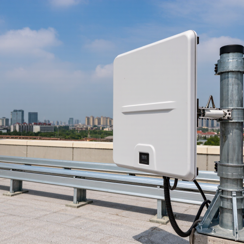
A directional antenna performs only as well as its mounting and alignment allow. Fix the mast to a rigid surface, not a flexible gutter or loose railing. Even slight movement can shift the main beam away from a distant site. Small errors matter. Set azimuth and elevation from verified site coordinates, then peak the signal using the receiver’s quality reading—not strength alone. ITU-R Recommendation P.525-4 gives free-space path loss as 32.45 + 20 log₁₀(frequency in MHz) + 20 log₁₀(distance in km). Use this estimate to understand the link budget, not as a promise of real-world performance.
Cable runs deserve equal attention. Check the cable’s attenuation table at your operating frequency, include connector losses, and keep the run short. A long, thin cable can erase gains from a higher-mounted antenna. If available, measure the completed run rather than trusting a label. I would also recheck alignment after tightening the mount; that step is easy to overlook. Walk the site for trees, roof edges, metal structures, and likely future obstructions. ITU-R Recommendations P.526 and P.833 address diffraction and vegetation effects, respectively. Wet foliage can alter a path, while nearby metal may distort the pattern. Note wind exposure, water entry, and corrosion risk before fixing the final position. A clean line of sight on installation day is not the whole story.
Check Compatibility, Durability, and Regulatory Limits
A directional antenna should match the radio’s frequency bands, connector, impedance, and polarization. Check the manual, not just the product label. A connector that looks right may still have the wrong gender or interface. I would not rely on a catalog’s maximum range; cable loss, mounting height, and nearby walls can change real performance.
For outdoor use, inspect the radome, seals, mounting hardware, and stated temperature range. ITU-R Recommendation P.837-7 provides R0.01 rainfall statistics: the rain rate exceeded for 0.01% of an average year. These data help assess rain-related propagation losses, especially on higher-frequency links. Water can still find a poor seal.
Regulatory limits depend on location, frequency, and equipment type. In the United States, FCC 47 CFR §15.247 sets a 1-watt conducted-power limit for certain digitally modulated systems, subject to antenna-gain and other conditions. That is not a universal allowance. Confirm the applicable local rules and the complete system’s permitted radiated power before installation; a higher-gain antenna can affect compliance even when the radio itself is unchanged.